Home
/ Refrigeration Cycle Diagram, Typical Vapor Compression Refrigeration Vcr Cycle Enggcyclopedia - In this final diagram of the refrigeration cycle we have introduced 3 new terms:
Refrigeration Cycle Diagram, Typical Vapor Compression Refrigeration Vcr Cycle Enggcyclopedia - In this final diagram of the refrigeration cycle we have introduced 3 new terms:
Refrigeration Cycle Diagram, Typical Vapor Compression Refrigeration Vcr Cycle Enggcyclopedia - In this final diagram of the refrigeration cycle we have introduced 3 new terms:. It tells us how much refrigerant the evaporator absorbs, the refrigerant properties in the compressor, and how much refrigerant the condenser rejects. The ordinary household refrigerator is a good example of the application of this cycle. It is a compression process, whose aim is to raise the refrigerant pressure, as it flows from an evaporator. For an air conditioning system to operate with economy, the refrigerant must be used repeatedly. It isn't a complete description by any means, but it is designed to assist a new technician or hvac/r apprentice in understanding the fundamentals.
This is a basic overview of the refrigeration circuit and how it works. Comparative performance study of vapour compression refrigeration system with r22/r134a/r410a/r407c/m20 | several refrigerants have emerged as substitutes to replace r22, the most widely used fluorocarbon refrigerants in the world. In this final diagram of the refrigeration cycle we have introduced 3 new terms: The red dots inside the piping represent discharge vapor. To jump to the part of this page that details the assumptions of a particular device or statepoint, just click on it.
Fault Diagnosis Of A Vapor Compression Refrigeration System With Hermetic Reciprocating Compressor Based On P H Diagram Sciencedirect from ars.els-cdn.com So refrigeration cycle should be known to understand the refrigeration system. Heat transfer from low to high temperature) cannot occur by itself (claussius definition of second law). The layout shown below is a clickable image. Pressurized refrigerant vapor condenses in the liquid state at constant pressure, rejection of heat to the environment. It isn't a complete description by any means, but it is designed to assist a new technician or hvac/r apprentice in understanding the fundamentals. The refrigerant flows into the compressor where it is compressed and pressurised. Description of a basic chiller refrigeration system: Understanding the basic refrigeration cycle diagram also helps us to find subcooled, superheat and to troubleshoot refrigeration processes much easier.
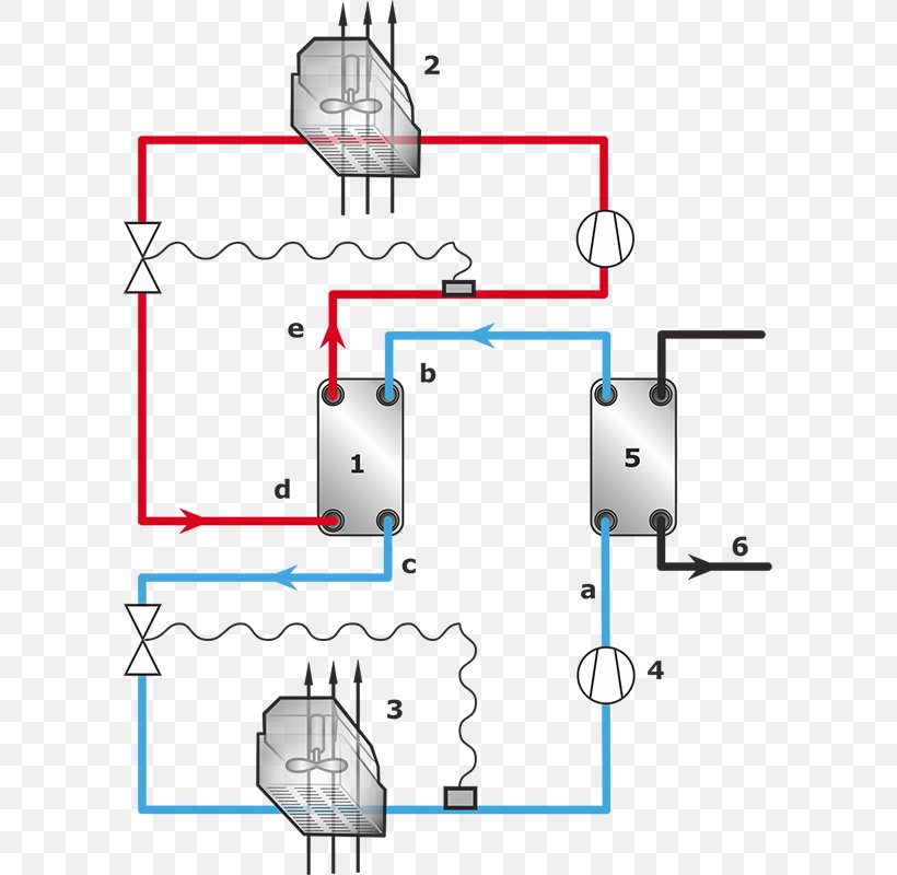
Component #2 in this refrigeration cycle diagram is the condenser.
Description of a basic chiller refrigeration system: At this point, the refrigerant is a hot gas. Vapour compression refrigeration system consists of four principal elements. To jump to the part of this page that details the assumptions of a particular device or statepoint, just click on it. Refrigeration cycle is the basis of all refrigeration systems. For an air conditioning system to operate with economy, the refrigerant must be used repeatedly. Hence the system is called a vapor compression. The refrigeration cycle starts and ends with the compressor. Compressor, condenser, expansion valve/throttle valve and evaporator. The vapor compression refrigeration cycle involves four components: It is a compression process, whose aim is to raise the refrigerant pressure, as it flows from an evaporator. They are compressor, condenser, expansion valve and evaporator. Pressurized refrigerant vapor condenses in the liquid state at constant pressure, rejection of heat to the environment.
The ordinary household refrigerator is a good example of the application of this cycle. The vapor compression refrigeration cycle involves four components: In this final diagram of the refrigeration cycle we have introduced 3 new terms: For refrigeration, the diagram is reduced to the relevant regions of liquid and gaseous as well as their mixed form. Description of a basic chiller refrigeration system:
Planning And Engineering Data 3 Fish Freezing 3 Processes And Equipment from www.fao.org Comparative performance study of vapour compression refrigeration system with r22/r134a/r410a/r407c/m20 | several refrigerants have emerged as substitutes to replace r22, the most widely used fluorocarbon refrigerants in the world. Compressor, condenser, expansion valve/throttle valve and evaporator. Vapour compression refrigeration system consists of four principal elements. 2.2 vapour compression cycle vapour compression cycle is an improved type of air refrigeration cycle in which a suitable. Pressurized refrigerant vapor condenses in the liquid state at constant pressure, rejection of heat to the environment. Refrigeration cycle it is a well known fact that heat flows in the direction of decreasing temperature, i.e., from a high temperature region to a low temperature region. The refrigeration cycle explains to us what is happening to the ac freon in each of the four components within the air conditioner units. This is a basic overview of the refrigeration circuit and how it works.
The refrigerant is then pushed to the condenser which turns the vapour into liquid and absorbs some of the heat.
2.2 vapour compression cycle vapour compression cycle is an improved type of air refrigeration cycle in which a suitable. In this final diagram of the refrigeration cycle we have introduced 3 new terms: It tells us how much refrigerant the evaporator absorbs, the refrigerant properties in the compressor, and how much refrigerant the condenser rejects. And the operating pressures will depend on the refrigerant being used and the desired evaporator temperature. This ensures the refrigerant is in a gas state with no liquid present. For an air conditioning system to operate with economy, the refrigerant must be used repeatedly. This portion indicates a pressure drop as there is a resistance of the suction valve to the compressor. Comparative performance study of vapour compression refrigeration system with r22/r134a/r410a/r407c/m20 | several refrigerants have emerged as substitutes to replace r22, the most widely used fluorocarbon refrigerants in the world. Understanding the basic refrigeration cycle diagram also helps us to find subcooled, superheat and to troubleshoot refrigeration processes much easier. For this reason, all air conditioners use the same cycle of compression, condensation. This is also done for mechanical reasons. Some basic refrigeration cycles are discussed here through different diagrams. The vapor compression refrigeration cycle involves four components:
So refrigeration cycle should be known to understand the refrigeration system. This portion indicates a pressure drop as there is a resistance of the suction valve to the compressor. In this final diagram of the refrigeration cycle we have introduced 3 new terms: This video is an animation of how the refrigeration cycle works, with each components function.هذا الفيديو هو الرسوم المتحركة لكيفية عمل دورة التبريد. Click on images to expand the view.
Diagram Heat Pump And Refrigeration Cycle System Schematic Png 800x800px Diagram Area Chiller Condenser Drawing Download from img.favpng.com To jump to the part of this page that details the assumptions of a particular device or statepoint, just click on it. Diagramme schnell und einfach erstellen. Liquids absorb heat when changed from liquid to gas. Click on images to expand the view. At this point, the refrigerant is a hot gas. Hence the system is called a vapor compression. There are two heat exchangers, one being the condenser which is hotter and releases heat and the other being the evaporator which is colder and accepts heat. 2.2 vapour compression cycle vapour compression cycle is an improved type of air refrigeration cycle in which a suitable.
Heat transfer from low to high temperature) cannot occur by itself (claussius definition of second law).
The ordinary household refrigerator is a good example of the application of this cycle. Description of a basic chiller refrigeration system: This is also done for mechanical reasons. This video is an animation of how the refrigeration cycle works, with each components function.هذا الفيديو هو الرسوم المتحركة لكيفية عمل دورة التبريد. At this point, the refrigerant is a hot gas. This is a basic overview of the refrigeration circuit and how it works. Gases give off heat when changed from gas to liquid. This portion indicates a pressure drop as there is a resistance of the suction valve to the compressor. Understanding the basic refrigeration cycle diagram also. This ensures the refrigerant is in a gas state with no liquid present. The 2 refrigeration cycles as explained below primarily differ in this process of vapor recovery. But the reverse process (i.e. The refrigeration cycle starts and ends with the compressor.